


Optinal
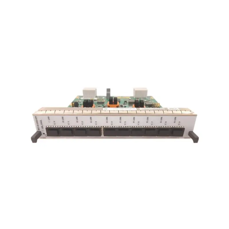


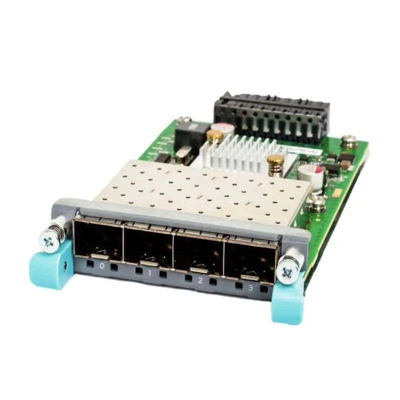
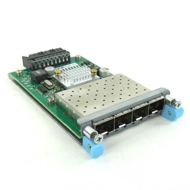
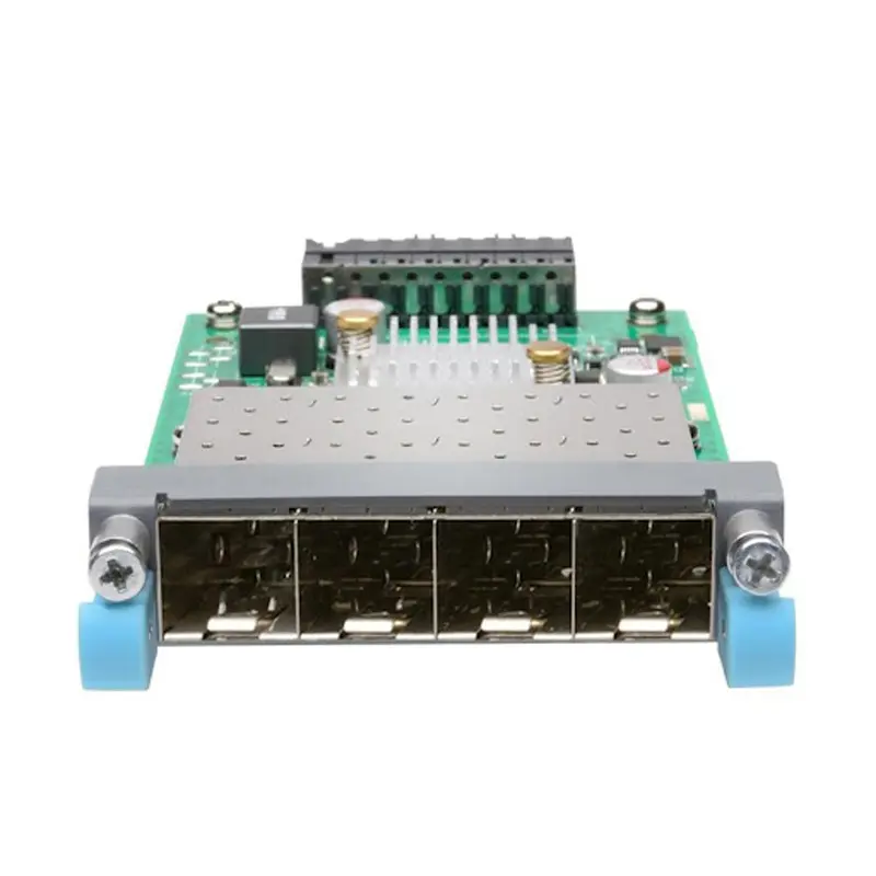
Juniper Uplink Module EX-UM-4X4SFP
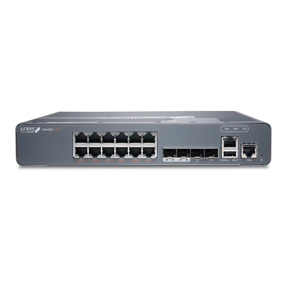
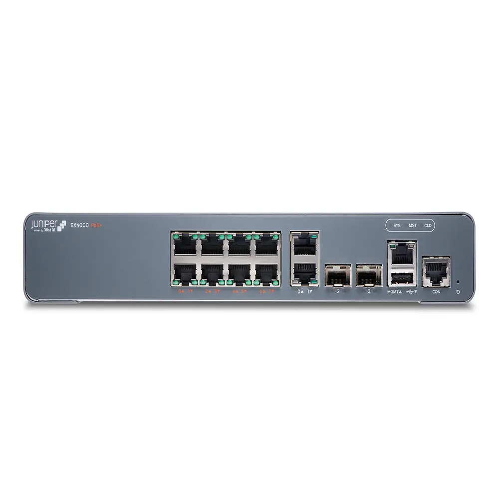
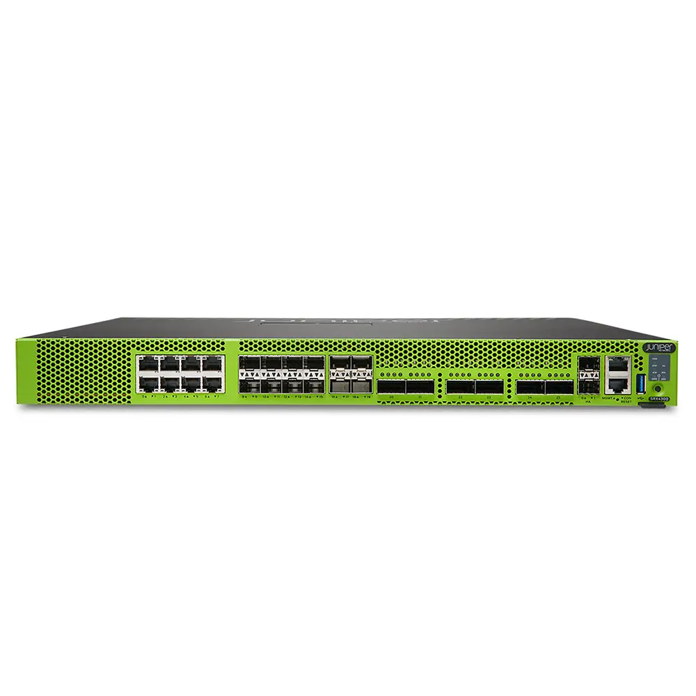
EX4300 Chassis
LCD Panel in EX4300 Switches
The LCD panel on the front panel of the EX4300 switch shows two lines of text, each with a maximum of 16 characters. The LCD panel displays a variety of information about the switch and also provides a menu to perform basic operations such as initial setup and reboot.
There are two navigation buttons—Menu and Enter—to the right of the LCD panel.
See Figure 1.
Figure 1: LCD Panel in EX4300 Switches
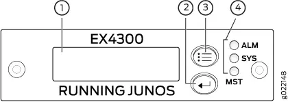
1 — LCD panel 3 — LCD panel Menu button
2 — LCD panel Enter button 4 — Chassis status LEDs
The first line of text on the LCD panel displays basic information about the switch and the second line of text displays information about the mode selected on the LCD panel. You can configure the second line of the text for the LCD panel to display a custom message. If the LCD panel is configured to display a custom message, the Menu button and the Enter button are disabled. See Configuring the LCD Panel on EX Series Switches (CLI Procedure).
The LCD panel has a backlight. If the LCD panel is idle for 60 seconds, the backlight turns off. You can turn on the backlight by pressing the Menu or Enter button once. After turning on the backlight, you can toggle between the LCD panel menus by pressing the Menu button and navigate through the menu options by pressing the Enter button.
Overview & Specifications Supported Platforms Supported Interface Modules Permalink
EX4300 Chassis
LCD Panel in EX4300 Switches
The LCD panel on the front panel of the EX4300 switch shows two lines of text, each with a maximum of 16 characters. The LCD panel displays a variety of information about the switch and also provides a menu to perform basic operations such as initial setup and reboot.
There are two navigation buttons—Menu and Enter—to the right of the LCD panel.
See Figure 1.
Figure 1: LCD Panel in EX4300 Switches 1 — LCD panel 3 — LCD panel Menu button
2 — LCD panel Enter button 4 — Chassis status LEDs
The first line of text on the LCD panel displays basic information about the switch and the second line of text displays information about the mode selected on the LCD panel. You can configure the second line of the text for the LCD panel to display a custom message. If the LCD panel is configured to display a custom message, the Menu button and the Enter button are disabled. See Configuring the LCD Panel on EX Series Switches (CLI Procedure).
The LCD panel has a backlight. If the LCD panel is idle for 60 seconds, the backlight turns off. You can turn on the backlight by pressing the Menu or Enter button once. After turning on the backlight, you can toggle between the LCD panel menus by pressing the Menu button and navigate through the menu options by pressing the Enter button.
LCD Panel Modes
The LCD panel operates in four modes: boot, idle, status, and maintenance.
The first line of text on the LCD panel displays the slot number, the role of the switch, and hostname in all the modes.
For a standalone EX4300 switch, by default the slot number is 00, and the role is RE.
In an EX4300 switch that is a member of a Virtual Chassis, the first line of the LCD panel always displays:
● The slot number (the member ID of the Virtual Chassis member)
● Role of the switch in the Virtual Chassis (RE for primary, BK for backup, and LC for line card member)
● Hostname